Toolbar and Menu Options
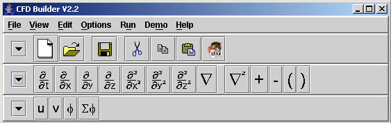
The CFD Builder contains 3 toolbars for creation of a computational simulation. The first is a Control Toolbar with data management tools and other basic application functions. The second is an Operator Toobar which contains predefined algebraic and partial differential equation operators for the purpose of building equations. The last is the Variable Toolbar, which contains user defined variables AND constants for the purpose of building equations. Each toolbar can be hidden when it is not required. Collapsing the toolbar is performed by pressing the "down arrow" to the left of the toolbar. The function of the Operator and Variable Toolbars is to place the operator, variable, or constant shown on the a button into a user specified text box. To do so, click the mouse button on the text box where the operator, variable, or constant should be placed. Then, press the appropriate button in the toolbar. Detail on how to defined variables and constants can be found in the Physical Parameters and Iteration Parameters section of this documentation.
Figure 1. Menu and Toolbar.
Menu Options
File
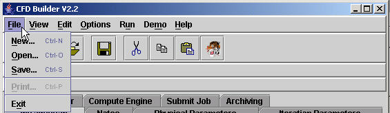
Figure 2. File Menu.
New clears out all fields in all tabs and windows.
Open gives the ability to open an existing file (produced by the GUI) residing in the local machine. It provides a File browser for easy navigation of files. Depending on the file opened, Iteration Parameters, Physical Parameters, Equation Builder, Preprocessed Data and Submit Job panels will be altered.
Save item saves all of the changes in Iteration Parameters, Physical Parameters, Preprocessed Data, Equation Builder and Submit Job, etc. (with the exception of password field) into a single file provided by the user. Currently files can be saved to the user's local machine only. Saved file can be opened using File->Open when needed.
Print will be offered in future versions.
Exit terminates the program.
View
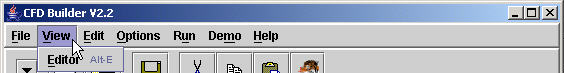
Figure 3. View Menu.
Edtor - The Editor Window will contain the compute engine specific script that is executed. The user may open a new Editor Window under this option and send miscellaneous commands to the server for pre- or post-processing. Editor files may be erased (New), opened, and , saved.
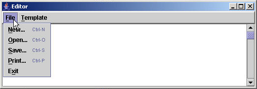
Figure 3a. Editor Window.
Edit
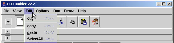
Figure 4. Edit Menu.
Cut allows athe user to remove a selection of text which may, or may not, be used later. This may not work in all fields. It's primary function is to aid equation building.
Copy makes a duplicate of text.
Paste places copied or cut text into a selected field.
Select All highlights all text in a selected field for cut, copy, or delete.
Options
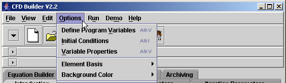
Figure 5. Options Menu.
Define Program Variables allows the user to define what the symbolic equation symbols will look like in the text script that the GUI creates. Once a set of simulation data is generated these variables are (by default) automatically updated when new scripts are generated. If variable names are extensively modified from the default variable settings, they should be saved in an external file for later retrieval. The automatic updates may be turned off in the Configuration Panel.
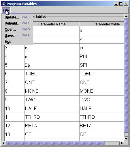
Figure 5a. Program Variables.
Initial Condition - Every dependent variable requires some initial condition. The GUI provides 2 options for entering this information. How this information is used is determined by the compute engine specific interface.
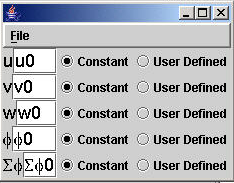
Figure 5b. Initial Conditions.
Variable Properties - Each dependent variable may have specific properties associated with it. A variable may be a scalar, or a vector, or it may have some other associations with it. These details are specified in the Variable Properties panel.
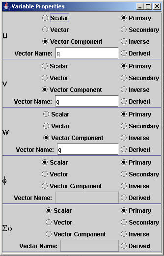
Figure 5. Variable Properties.
Element Basis - The current GUI allows for algortihm basis selection to be passed to the compute engine interface. Note that the GUI is a generic tool that provides a wide range of options for multiple compute engine capability. The GUI provides options for the linear, quadratic, cubic, and Hermite basis, but this does not mean that the compute engine can support a Hermite basis. It is the user's responsibility to know what the compute engine can support.
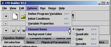
Figure 5d. Element Basis.
Background Color changes the background color of text boxes and tables for readability. More sophisticated user options will be applied to future releases.
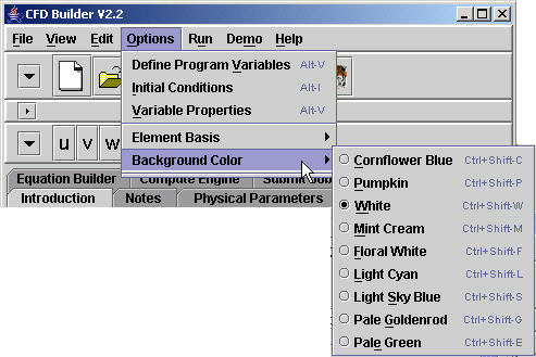
Figure 5e. Background Color.
Run

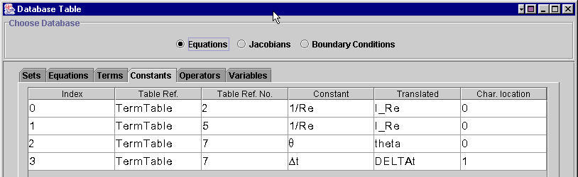
Figure 6. Run Menu.
Build Database - The GUI is base on a database system. The equations, jacobians, and boundary conditions are analyzed by the GUI to build a database that is then sent to a compute engine specific interface that creates the script specific to that compute engine. Once all parameters and equations are entered the database must be built before the compute engine can be executed.
View Database - The user has complete control over what information is sent to the compute engine interface. It is the user's responsibility to view the database information and confirm that the GUI has interpreted the equations as the user intends (Figure 6a). If the GUI has mis-interpreted the equations, the database can be altered by hand. These revisions will be sent to the compute engine interface. Any revisions made in the database will be lost on the next "Build Database" process.
Figure 6a. View Database.
View Template
After all equations, parametric data, and data management information have been entered, a compute engine specific script is generated by the GUI. This "template" may be viewed by through the View Template option.

Figure 6b. Viewing the GUI generated script.
Refresh Template
Anytime a change is made to equations, parameters, or data management information in the GUI, the GUI must be informed of the changes so that it can update the script. This termed "Refreshing the template".
Run/Submit Template, Clear Status Window
These options are duplicate functions of the buttons in the Submit Panel. See Submit Panel for more details.
Demo
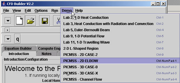
Figure 7. Demo Menu.
Several demonstrations are available. Click on the desired example and all necessary fields will be filled in.
NOTE ***** This does not include configuration of the GUI for local or remote access. Configuration to run a simulation is required by the user each time the GUI is opened.
Help
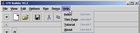
Figure 8. Help Menu.
Index displays links to help pages for all of the panels and tutorials.
This Page shows the help page for currently active panel.
Tutorial refers users to sets of tutorials for using this application.
About item gives general information about the PICMSS project.
Toolbar
New is equivalent to New item in the File Menu. See Menu Options above for more information.
Open is equivalent to Open item in the File Menu. See Menu Options above for more information.
Save is equivalent to Save item in the File Menu. See Menu Options above for more information.
Cut, Copy, Paste are equivalent to Cut, Copy and Paste items in the File Menu. See Menu Options above for more information.
Greek button on the toolbar is required to build equations when Greek symbols are required in the equations. This button opens a panel displaying upper and lower case greek symbols.
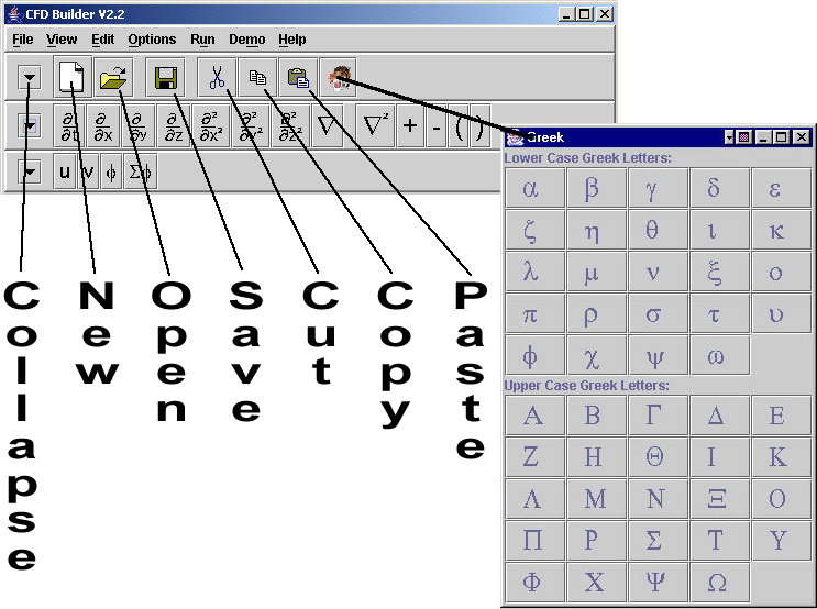
Figure 9. Greek and Operator Buttons in the toolbar.